Overview
Decodingisthereverseprocessofencoding.Duringencoding,eachbinarycodeisassignedaspecificmeaning,thatis,itrepresentsacertainsignalorobject.Theprocessof"translating"thespecificmeaningofthecodestateiscalleddecoding,andthecircuitthatimplementsthedecodingoperationiscalledadecoder.Inotherwords,adecoderisacircuitthatcantranslatethestateoftheinputbinarycodeintoanoutputsignaltoexpressitsoriginalmeaning.
Според нуждите изходният сигнал може да бъде импулсен, високо или ниско ниво.
Classification
Therearemanytypesofdecoders,buttheirworkingprinciplesandanalysisanddesignmethodsaresimilar.Amongthem,binarydecoders,two-decimaldecodersanddisplaydecodersTheyarethethreemosttypicalandwidelyuseddecodingcircuits.
Binarycodedecoder,alsocalledminimumitemdecoder,takeonedecoderfromN,theminimumitemdecodergenerallytranslatesbinarycodeintodecimalcode;
Декодер за преобразуване на код, който преобразува от един код в друг код;
Displaydecoder,generallytranslatesacodeintoadecimalcodeoraspecificcode,andpassesthedisplaydeviceDisplaythestatusofthedecoder.
VariableDecoding
Thevariabledecoderisacombinationallogiccircuitwithmultipleoutputterminalsthattransformsninputsinto2^noutputs.Themodelcanberepresentedbythefollowingfigure.Amongallthecombinationsofinputchanges,eachoutputis1onlyonce.Sincetheminimumitemis1onlyonceinthetruthtable,theoutputistheminimumitemoftheinputvariable.combination.Therefore,thedecodercanalsobecalledtheminimumtermgeneratorcircuit.
Workingprinciple
Thedecoderisalogiccircuitwitha"translation"function.ThiscircuitcantranslatethevariousstatesoftheinputbinarycodeintocorrespondingTheoutputsignal.Somedecodersareequippedwithoneormoreenablecontrolinputterminals,whichbecomechipselectterminalstocontrolwhetherdecodingisallowedorprohibited.
На фигура 1 74138 е 3-жилен-8-жичен декодер. Трите входни терминала CBA имат общо 8 комбинации от състояния (000-111), които могат да декодират 8 изходни сигнали Y0—Y7. Този вид декодер има три активирани входни терминала. Когато G2A и G2 Bareboth0 и G1 е 1, декодирането не работи Когато декодирането е деактивирано, то извежда високо ниво.
InFigure2,thecircuitfordetectingthetimewaveformofthe74ls138decoderusesadigitalsignalgeneratorandalogicanalyzer.Thedigitalsignalgeneratorsendsouttwosetsof000-111squarewavesignalsinsequenceinonecycle.
Фигура 3 показва как да свържете два 3-жични-8-жични декодера към 4-жилен-16-жичен декодер. Активиращият терминал G1 на втория чип74138 и активиращият терминал G2A на първия чип са свързани към входния терминал D. Когато D=0, първата част от 74138 работи и декодира и извежда входния знак alof0000-0111. Когато D=1, този втори чип 74138 работи за декодиране и извежда входния сигнал от 1000-1111.
InFigure4,7442isabinary-decimaldecoderwith4inputterminalsand10outputterminals.Theinputsignaladopts8421BCDcode,andthebinarynumber0000-1001correspondstothedecimalnumber0-9.Whentheinputexceedsthisrange,itisinvalid,andthe10outputterminalsareallhigh.The7442circuithasnoenableterminal,soaslongastheinputiswithinthespecifiedrange,therewillbeanoutputterminalthatislow.
Picture5bitBCD—sevensegmentdisplaydecodercircuit,LEDdigitaltubewilldisplaythedecimalnumber0-9correspondingtotheBCDcode.Becausethedisplaydecodercircuitoutputsahighlevel,acommoncathodeLEDdigitaltubeshouldbeused.
Theprocessofencodinganddecodingisjusttheopposite.Theencodercangenerateasetofbinarycodesforavalidinputsignal.Someencodersareequippedwithanenableterminaltocontrolwhetherencodingisallowedorprohibited.
Thefunctionofthepriorityencoderistoallowinputsignalsatseveralinputterminalsatthesametime.Theencoderisarrangedaccordingtothepriorityorderoftheinputsignals,andonlyperformsprocessingontheonewiththehighestpriorityamongtheseveralsignalsinputatthesametime.coding.InFigure6,74147isaBCDpriorityencoder,bothinputandoutputareactivelow.Inordertoobtainaneffectiveoutputhighlevel,aninvertercanbeconnectedtoeachoutputterminal.7417hasonly1-9eachinputterminal,0inputterminalisnotconnectedtothecircuit.Thisisbecause7417stipulatesthatwhenthereisnovalidinput,theBCDcode0000of0isoutput.
Figure7isalogiccircuitthatdetectsthepriorityencoding/decodingfunction.Foreachgroundedlogicswitch,thedigitaltubewilldisplayacorrespondingdecimalnumber.Amongthe8logicswitchesattheinput,theprioritywiththecodename[7]isthehighest,andtheprioritywiththecode[0]isthelowest.
Обяснете
Структурата на веригата за декодиране
Фигура 1
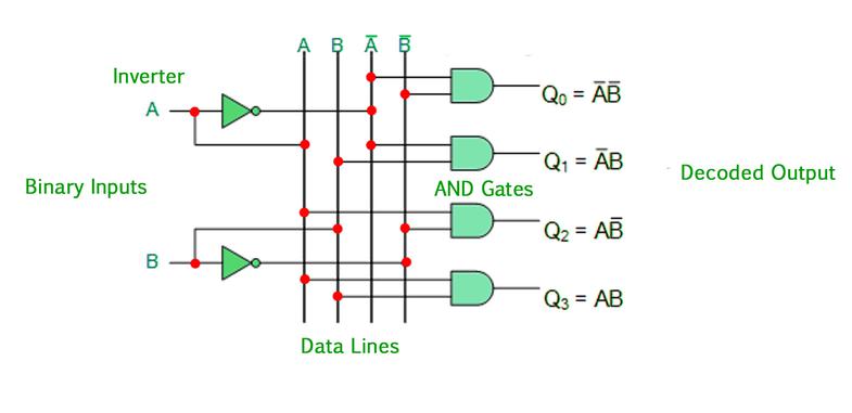
IamdiscussingthefunctionofthedecoderLet’stakealookattheinternalstructureofthedecoder.Thefigurebelowisa2-inputdecodermainlycomposedofANDgatecircuits,withatotalof22outputs(thatis,4).Fromthefigure,eachoutputcorrespondstoone.Thesmallestitem.Inthiscircuit,whenthevalueoftheinputBAis10,whichcorrespondstothedecimalnumber2,itsF2outputishigh,andtherestoftheoutputis0.
Снимка 2
Thepicturebelowisalsoa2-inputdecoder,butbecauseitmainlyusesaNANDgate,eachTheoutputcorrespondstothenegationofaminimumterm.Inthiscircuit,whentheinputBAis10,itsoutputF2isnolonger1,buttheoutputis0,andtheremainingoutputsare1.
Weregardthefollowingdecodercircuitastheoutputlowleveleffective(thatis,whentheinputvariablecorrespondstothedecimali,thecorrespondingi-thoutputterminalislowlevel,andtherestarehighLevel).Ofcourse,thepreviousdecoderisactiveathighlevel.
Фигура 3
Thetwocircuitslistedabovearethecaseof2inputs,andthesameistrueforthecaseofmorethan2inputs,thesameItcanoutputhigh-leveleffective,andoutputlow-leveleffective.

Realizelogicfunctionwithdecoder
Becauseanycombinationallogiccircuitcanbewrittenintheformofminimumtermexpression,theoutputofthedecodercircuitliststhecircuit’sAllminimumtermexpressions(ornon-expressionofminimumterms),sowemayusedecodercircuitstoimplementvariouscombinationallogiccircuits.
Примерът използва декодиращата схема за реализиране на F(X,Y,Z)=∑(0,1,4,6,7)=∏M(2,3,5)
Wecanimplementthislogicfunctioninseveralways.Thefollowingfigurelistsfourmethods.Fromthesefourfigures,youshouldbeabletosummarizetherules.
Сред тях:
Pictureaistherealizationmethodofhigh-leveleffectiveoutputplusORgate;
Picturebisthelow-leveleffectiveoutputplusNANDgate
Figurecistheimplementationmethodofhigh-leveleffectiveoutputplusNORgate;
Figuredistheimplementationmethodoflow-leveleffectiveoutputplusNANDgate;
Фигура 4
EnableInputs
Enablesareoftenencounteredinmedium-scaleintegratedcircuitsTheenablepincanbeinputoroutput.Itistheinput/outputterminalusedtoexpandthefunctionofthemedium-scaleintegratedcircuit.Thefollowingfigureaisa2-inputdecoderwithaninputE,DuetotheadditionoftheinputterminalE,itsfunctionhaschanged.WhenE=0,itsoutputisall0,andthedecoderisactiveathighlevelwhentheEterminalisnotadded.Atthistime,itsoutputNoneoftheterminalsisinavalidworkingstate,wecanunderstandthatwhenE=0,thedecoderdoesnotwork;whenE=1,weseethatthedecodercanworknormally,weputthisinputterminalinEWhen=1,theenableterminalthatcanworknormallyiscalledactivehigh.Thefigurebbelowisasimplifiedlogicalsymbol.
Фигура 5
Thefigurebelowisanexampleofusingtheenableterminaltoconverttwo2-inputdecodersinto3-inputdecoders.Inthefigurebelow,whenI2islow,theenableterminalofthefirstdecoderishighanditworksnormally,buttheseconddecoderdoesnotworkatthistime,sotheoutputofdecoder1correspondstoInput0~3ofI3I2I1;whenI2ishigh,decoder2works,anddecoder1doesnotwork,soitsoutputcorrespondstoinput4~7ofI2I1I0,sothecircuitinthefigurebelowrealizestheuseoftheenableterminalExtenda2-inputdecodertoa3-inputdecoder.
Фигура 6
Стандартна декодираща схема със среден мащаб
Има няколко вида декодери в интегрираните схеми със среден мащаб, като най-широко използваният е 74138, който е декодер от 3 до 8. Следните фигури показват неговите логически символи и подреждане на пина. Логическата функция на устройството е изброена в таблицата по-долу, което може да се види от таблицата. Неговият изход е активен на ниско ниво, позволява на терминал G1 е активен на високо ниво,/G2,/G3 е активен на ниско ниво, когато някой от тях е на ниско ниво, изходните терминали са реални1.
Фигура 7
Например използвайте74138, за да реализирате функциятаF(X,Y,Z)=∑m(0,2,4,7)
p>
Using74138torealizethefunctionisthesameastheabove-mentioneddecodertorealizethelogicfunction,buttwopointsmustbepaidattentionto:
Theoutputof1.74138islow-leveleffective,sothelogicfunctionisrealizedWhentheoutputterminalcannotbeconnectedtoORgateandNORgate(becauseonlyoneislowleveleachtime,therestarehighlevel);
2.74138differsfromthepreviousoneinthatithasanenableterminal,Sotheenableterminalmustbeprocessed,otherwisetherequiredlogicfunctioncannotberealized.Thefollowingfigureshowsthefinalcircuit.
Фигура 8
Декодиране на дисплея
Theworkingprincipleofcommonlyuseddisplaydevices
Commondigitaldisplaysindigitalsystemsusuallyinclude:light-emittingdiodenixietubes(LEDnixietubes)andliquidcrystaldisplaynixietubes(LCDnixietubes).TheLEDdigitaltubeuseslight-emittingdiodestoformstrokesfordisplayingnumberstodisplaynumbers.BecausetheLEDsemitlight,theLEDdigitaltubeissuitableforvariousoccasions.Theliquidcrystaldisplaydigitaltubeusestheliquidcrystalmaterialtoabsorblightundertheactionofalternatingvoltage,andthereisnostrokewithouttheactionofthealternatingelectricfield,soitcandisplaythenumber,butbecausetheliquidcrystalmaterialmusthavelightItcanonlybeused,soitcannotbeusedinsituationswherethereisnooutsidelight(theLCDdisplayofportablecomputerscanbeusedatnightundertheactionofbacklight),butthebiggestadvantageofLCDisthatitconsumesalotofelectricity,soitiswidelyusedinDigitaldisplayofsmalldevicessuchassmallcalculators.
ThefollowingfigureshowstheinternalstructureoftheLEDdigitaltubeandthedisplayofthenumber.ItisakindofLEDdigitaltubewithananodeconnectedinone.Weusuallycallitacommonanodedigitaltube.Sincethereisacommonanodedigitaltube,thereisacommoncathodedigitaltube.Theinternalstructureisnotdrawnhere.Pleasedrawityourself.
Фигура 9
Светодиодна декодираща задвижваща верига
Трябва да се включи само диод, излъчващ светлина. Според това дали общият полюс на LEDisananodeorakatod е разделен на два типа декодери, т.е.
4511isaneffectivehigh-levelCMOSdisplaydecoder,itsinputis8421BCDcode,thefollowingfigureandtablerespectively4511pinarrangement,logicsymbolsandlogicfunctiontable.
Фигура 10
На фигурата:
/LT:Тестов кол на лампата,ниско нивоефективен,когато е с ниска мощностОбикновено,всички удари сареални.Ако сане,това означава,че има проблем с удара;
/BL:Светлината е изключена,ниско нивоактивно,когато ениско ниво,независимо отсъстоянието на въведените данни,изходът евсички ниско ниво,т.е.всички щрихи са изгасени;
/ST/LE:strobe/latchpole,whichisamultiplexedfunctionalterminal,whentheinputislow,itsoutputandTheinputvariableisrelated;whentheinputishigh,itsoutputisonlyrelatedtothestatebeforetheendishigh,andnomatterhowtheinputDCBAterminalchanges,itsdisplayedvalueremainsunchanged.
D,C,B,A:8421BCDcodeinput,theDbitisthemostbit;
a~g: изходният терминал е с високо ниво на ефективност, така че изходите му трябва да съответстват на цифровата тръба с нейния катод.
LCDdecoderdriver
TheLCDdecoderdrivercircuitisdifferentfromtheLEDdecoderdrivercircuit.Itsoutputisnotahighleveloralowlevel,butapulsevoltage.Whenitisvalid,itsoutputisalternatingpulsevoltage,otherwiseitishighlevelorlowlevel.
