Overview
Decodingisthereverseprocessofencoding.Duringencoding,eachbinarycodeisassignedaspecificmeaning,thatis,itrepresentsacertainsignalorobject.Theprocessof"translating"thespecificmeaningofthecodestateiscalleddecoding,andthecircuitthatimplementsthedecodingoperationiscalledadecoder.Inotherwords,adecoderisacircuitthatcantranslatethestateoftheinputbinarycodeintoanoutputsignaltoexpressitsoriginalmeaning.
Podle požadavků může být výstupní signál pulzní, vysoká nebo nízká úroveň.
Classification
Therearemanytypesofdecoders,buttheirworkingprinciplesandanalysisanddesignmethodsaresimilar.Amongthem,binarydecoders,two-decimaldecodersanddisplaydecodersTheyarethethreemosttypicalandwidelyuseddecodingcircuits.
Binarycodedecoder,alsocalledminimumitemdecoder,takeonedecoderfromN,theminimumitemdecodergenerallytranslatesbinarycodeintodecimalcode;
Dekodér převodu kódu, který převádí z jednoho kódu na jiný kód;
Displaydecoder,generallytranslatesacodeintoadecimalcodeoraspecificcode,andpassesthedisplaydeviceDisplaythestatusofthedecoder.
VariableDecoding
Thevariabledecoderisacombinationallogiccircuitwithmultipleoutputterminalsthattransformsninputsinto2^noutputs.Themodelcanberepresentedbythefollowingfigure.Amongallthecombinationsofinputchanges,eachoutputis1onlyonce.Sincetheminimumitemis1onlyonceinthetruthtable,theoutputistheminimumitemoftheinputvariable.combination.Therefore,thedecodercanalsobecalledtheminimumtermgeneratorcircuit.
Workingprinciple
Thedecoderisalogiccircuitwitha"translation"function.ThiscircuitcantranslatethevariousstatesoftheinputbinarycodeintocorrespondingTheoutputsignal.Somedecodersareequippedwithoneormoreenablecontrolinputterminals,whichbecomechipselectterminalstocontrolwhetherdecodingisallowedorprohibited.
Na obrázku 1,74138 je 3vodičový-8vodičový dekodér.TřivstupnísvorkyCBAmajícelkem8kombinacístavů(000-111),kterédokážoudekódovat8výstupníchsignálůY0–Y7.Tento druh dekódování lze zadat pouze ze tří vstupních svorek a v1stavu G2 funguje 2B. Je-li dekódování deaktivováno, výstup má vysokou úroveň.
InFigure2,thecircuitfordetectingthetimewaveformofthe74ls138decoderusesadigitalsignalgeneratorandalogicanalyzer.Thedigitalsignalgeneratorsendsouttwosetsof000-111squarewavesignalsinsequenceinonecycle.
Obrázek 3 ukazuje, jak připojit dva 3vodičové 8vodičové dekodéry do 4vodičového 16vodičového dekodéru. Povolení terminálu G1 druhého čipu 74138 a povolení terminálu G2 A prvního čipu se připojí k terminálu digitálního vstupu a připojí se kus D=740, první 00-0111. Když D=1, druhý čip74138 pracuje na dekódování a vydává vstupní signál 1000-1111.
InFigure4,7442isabinary-decimaldecoderwith4inputterminalsand10outputterminals.Theinputsignaladopts8421BCDcode,andthebinarynumber0000-1001correspondstothedecimalnumber0-9.Whentheinputexceedsthisrange,itisinvalid,andthe10outputterminalsareallhigh.The7442circuithasnoenableterminal,soaslongastheinputiswithinthespecifiedrange,therewillbeanoutputterminalthatislow.
Picture5bitBCD—sevensegmentdisplaydecodercircuit,LEDdigitaltubewilldisplaythedecimalnumber0-9correspondingtotheBCDcode.Becausethedisplaydecodercircuitoutputsahighlevel,acommoncathodeLEDdigitaltubeshouldbeused.
Theprocessofencodinganddecodingisjusttheopposite.Theencodercangenerateasetofbinarycodesforavalidinputsignal.Someencodersareequippedwithanenableterminaltocontrolwhetherencodingisallowedorprohibited.
Thefunctionofthepriorityencoderistoallowinputsignalsatseveralinputterminalsatthesametime.Theencoderisarrangedaccordingtothepriorityorderoftheinputsignals,andonlyperformsprocessingontheonewiththehighestpriorityamongtheseveralsignalsinputatthesametime.coding.InFigure6,74147isaBCDpriorityencoder,bothinputandoutputareactivelow.Inordertoobtainaneffectiveoutputhighlevel,aninvertercanbeconnectedtoeachoutputterminal.7417hasonly1-9eachinputterminal,0inputterminalisnotconnectedtothecircuit.Thisisbecause7417stipulatesthatwhenthereisnovalidinput,theBCDcode0000of0isoutput.
Figure7isalogiccircuitthatdetectsthepriorityencoding/decodingfunction.Foreachgroundedlogicswitch,thedigitaltubewilldisplayacorrespondingdecimalnumber.Amongthe8logicswitchesattheinput,theprioritywiththecodename[7]isthehighest,andtheprioritywiththecode[0]isthelowest.
Vysvětlení
Struktura obvodu dekodéru
Obrázek 1
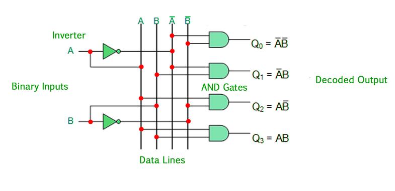
IamdiscussingthefunctionofthedecoderLet’stakealookattheinternalstructureofthedecoder.Thefigurebelowisa2-inputdecodermainlycomposedofANDgatecircuits,withatotalof22outputs(thatis,4).Fromthefigure,eachoutputcorrespondstoone.Thesmallestitem.Inthiscircuit,whenthevalueoftheinputBAis10,whichcorrespondstothedecimalnumber2,itsF2outputishigh,andtherestoftheoutputis0.
Obrázek2
Thepicturebelowisalsoa2-inputdecoder,butbecauseitmainlyusesaNANDgate,eachTheoutputcorrespondstothenegationofaminimumterm.Inthiscircuit,whentheinputBAis10,itsoutputF2isnolonger1,buttheoutputis0,andtheremainingoutputsare1.
Weregardthefollowingdecodercircuitastheoutputlowleveleffective(thatis,whentheinputvariablecorrespondstothedecimali,thecorrespondingi-thoutputterminalislowlevel,andtherestarehighLevel).Ofcourse,thepreviousdecoderisactiveathighlevel.
Obrázek 3
Thetwocircuitslistedabovearethecaseof2inputs,andthesameistrueforthecaseofmorethan2inputs,thesameItcanoutputhigh-leveleffective,andoutputlow-leveleffective.

Realizelogicfunctionwithdecoder
Becauseanycombinationallogiccircuitcanbewrittenintheformofminimumtermexpression,theoutputofthedecodercircuitliststhecircuit’sAllminimumtermexpressions(ornon-expressionofminimumterms),sowemayusedecodercircuitstoimplementvariouscombinationallogiccircuits.
Příklad používá dekódovací obvod k realizaci F(X,Y,Z)=∑(0,1,4,6,7)=∏M(2,3,5)
Wecanimplementthislogicfunctioninseveralways.Thefollowingfigurelistsfourmethods.Fromthesefourfigures,youshouldbeabletosummarizetherules.
Mezi ně:
Pictureaistherealizationmethodofhigh-leveleffectiveoutputplusORgate;
Obrázek představuje efektivní výstup na nízké úrovni a bránu NAND
Figurecistheimplementationmethodofhigh-leveleffectiveoutputplusNORgate;
Figuredistheimplementationmethodoflow-leveleffectiveoutputplusNANDgate;
Obrázek 4
EnableInputs
Enablesareoftenencounteredinmedium-scaleintegratedcircuitsTheenablepincanbeinputoroutput.Itistheinput/outputterminalusedtoexpandthefunctionofthemedium-scaleintegratedcircuit.Thefollowingfigureaisa2-inputdecoderwithaninputE,DuetotheadditionoftheinputterminalE,itsfunctionhaschanged.WhenE=0,itsoutputisall0,andthedecoderisactiveathighlevelwhentheEterminalisnotadded.Atthistime,itsoutputNoneoftheterminalsisinavalidworkingstate,wecanunderstandthatwhenE=0,thedecoderdoesnotwork;whenE=1,weseethatthedecodercanworknormally,weputthisinputterminalinEWhen=1,theenableterminalthatcanworknormallyiscalledactivehigh.Thefigurebbelowisasimplifiedlogicalsymbol.
Obrázek 5
Thefigurebelowisanexampleofusingtheenableterminaltoconverttwo2-inputdecodersinto3-inputdecoders.Inthefigurebelow,whenI2islow,theenableterminalofthefirstdecoderishighanditworksnormally,buttheseconddecoderdoesnotworkatthistime,sotheoutputofdecoder1correspondstoInput0~3ofI3I2I1;whenI2ishigh,decoder2works,anddecoder1doesnotwork,soitsoutputcorrespondstoinput4~7ofI2I1I0,sothecircuitinthefigurebelowrealizestheuseoftheenableterminalExtenda2-inputdecodertoa3-inputdecoder.
Obrázek 6
Standardní obvod dekodéru středního měřítka
V integrovaných obvodech středního měřítka existuje několik typů dekodérů. Nejpoužívanější je 74138, což je 3 až 8 dekodér. Následující obrázek ukazuje logické symboly a nízké uspořádání. aktivní, povolit terminál G1 na vysoké úrovni aktivní,/G2,/G3 je na nízké úrovni aktivní, pokud je některá z nesprávně nízké úrovně, jsou všechny výstupní terminály1.
Obrázek 7
Například použijte74138k realizaci funkceF(X,Y,Z)=∑m(0,2,4,7)
p>
Using74138torealizethefunctionisthesameastheabove-mentioneddecodertorealizethelogicfunction,buttwopointsmustbepaidattentionto:
Theoutputof1.74138islow-leveleffective,sothelogicfunctionisrealizedWhentheoutputterminalcannotbeconnectedtoORgateandNORgate(becauseonlyoneislowleveleachtime,therestarehighlevel);
2.74138differsfromthepreviousoneinthatithasanenableterminal,Sotheenableterminalmustbeprocessed,otherwisetherequiredlogicfunctioncannotberealized.Thefollowingfigureshowsthefinalcircuit.
Obrázek 8
Dekódování zobrazení
Theworkingprincipleofcommonlyuseddisplaydevices
Commondigitaldisplaysindigitalsystemsusuallyinclude:light-emittingdiodenixietubes(LEDnixietubes)andliquidcrystaldisplaynixietubes(LCDnixietubes).TheLEDdigitaltubeuseslight-emittingdiodestoformstrokesfordisplayingnumberstodisplaynumbers.BecausetheLEDsemitlight,theLEDdigitaltubeissuitableforvariousoccasions.Theliquidcrystaldisplaydigitaltubeusestheliquidcrystalmaterialtoabsorblightundertheactionofalternatingvoltage,andthereisnostrokewithouttheactionofthealternatingelectricfield,soitcandisplaythenumber,butbecausetheliquidcrystalmaterialmusthavelightItcanonlybeused,soitcannotbeusedinsituationswherethereisnooutsidelight(theLCDdisplayofportablecomputerscanbeusedatnightundertheactionofbacklight),butthebiggestadvantageofLCDisthatitconsumesalotofelectricity,soitiswidelyusedinDigitaldisplayofsmalldevicessuchassmallcalculators.
ThefollowingfigureshowstheinternalstructureoftheLEDdigitaltubeandthedisplayofthenumber.ItisakindofLEDdigitaltubewithananodeconnectedinone.Weusuallycallitacommonanodedigitaltube.Sincethereisacommonanodedigitaltube,thereisacommoncathodedigitaltube.Theinternalstructureisnotdrawnhere.Pleasedrawityourself.
Obrázek 9
Hnací obvod dekódování LED
Světlo emitující diodu je třeba pouze zapnout. Podle toho, zda je společný pól LEDaanodenebokatoda rozdělen do dvou typů dekodérů,tedynízkoúrovňovývalidnídekodérprojednosměrnoukatoduLED;platný.vysokoúrovňovýkód
4511isaneffectivehigh-levelCMOSdisplaydecoder,itsinputis8421BCDcode,thefollowingfigureandtablerespectively4511pinarrangement,logicsymbolsandlogicfunctiontable.
Obrázek 10
Na obrázku:
/LT:Zkušební pól,nízká účinnost,při nízkém výkonu Normálně jsou všechny úhozy skutečné.Pokud nejsou, znamená to, že je problém se zdvihem;
/BL:Světlo vypnuté,nízkáúroveňaktivní,přinízkéúrovni,bez ohledu na stav vstupních dat,jehovýstup je povolenáúroveň,takževšechnyúderyvyhasnou;
/ST/LE:strobe/latchpole,whichisamultiplexedfunctionalterminal,whentheinputislow,itsoutputandTheinputvariableisrelated;whentheinputishigh,itsoutputisonlyrelatedtothestatebeforetheendishigh,andnomatterhowtheinputDCBAterminalchanges,itsdisplayedvalueremainsunchanged.
D,C,B,A:8421BCDvstup kódu,největšíbitDbit;
a~g:výstupní terminál je vysoce účinný, takže výstupy by měly odpovídat digitální trubici s její katodou.
LCDdecoderdriver
TheLCDdecoderdrivercircuitisdifferentfromtheLEDdecoderdrivercircuit.Itsoutputisnotahighleveloralowlevel,butapulsevoltage.Whenitisvalid,itsoutputisalternatingpulsevoltage,otherwiseitishighlevelorlowlevel.
