Overview
Decodingisthereverseprocessofencoding.Duringencoding,eachbinarycodeisassignedaspecificmeaning,thatis,itrepresentsacertainsignalorobject.Theprocessof"translating"thespecificmeaningofthecodestateiscalleddecoding,andthecircuitthatimplementsthedecodingoperationiscalledadecoder.Inotherwords,adecoderisacircuitthatcantranslatethestateoftheinputbinarycodeintoanoutputsignaltoexpressitsoriginalmeaning.
Accordingtoneeds,theoutputsignalcanbepulse,highlevelorlowlevel.
Classification
Therearemanytypesofdecoders,buttheirworkingprinciplesandanalysisanddesignmethodsaresimilar.Amongthem,binarydecoders,two-decimaldecodersanddisplaydecodersTheyarethethreemosttypicalandwidelyuseddecodingcircuits.
Binarycodedecoder,alsocalledminimumitemdecoder,takeonedecoderfromN,theminimumitemdecodergenerallytranslatesbinarycodeintodecimalcode;
Codeconversiondecoder,whichconvertsfromonecodetoanothercode;
Displaydecoder,generallytranslatesacodeintoadecimalcodeoraspecificcode,andpassesthedisplaydeviceDisplaythestatusofthedecoder.
VariableDecoding
Thevariabledecoderisacombinationallogiccircuitwithmultipleoutputterminalsthattransformsninputsinto2^noutputs.Themodelcanberepresentedbythefollowingfigure.Amongallthecombinationsofinputchanges,eachoutputis1onlyonce.Sincetheminimumitemis1onlyonceinthetruthtable,theoutputistheminimumitemoftheinputvariable.combination.Therefore,thedecodercanalsobecalledtheminimumtermgeneratorcircuit.
Workingprinciple
Thedecoderisalogiccircuitwitha"translation"function.ThiscircuitcantranslatethevariousstatesoftheinputbinarycodeintocorrespondingTheoutputsignal.Somedecodersareequippedwithoneormoreenablecontrolinputterminals,whichbecomechipselectterminalstocontrolwhetherdecodingisallowedorprohibited.
InFigure1,74138isa3-wire-8-wiredecoder.ThethreeinputterminalsCBAhaveatotalof8statecombinations(000-111),whichcandecode8outputsignalsY0—Y7.Thiskindofdecoderhasthreeenableinputterminals.WhenG2AandG2Bareboth0andG1is1,thedecoderisinworkingstateandoutputslowlevel.Whenthedecoderisdisabled,itoutputsahighlevel.
InFigure2,thecircuitfordetectingthetimewaveformofthe74ls138decoderusesadigitalsignalgeneratorandalogicanalyzer.Thedigitalsignalgeneratorsendsouttwosetsof000-111squarewavesignalsinsequenceinonecycle.
Figure3showshowtoconnecttwo3-wire-8-wiredecodersintoa4-wire-16-wiredecoder.TheenablingterminalG1ofthesecondchip74138andtheenablingterminalG2AofthefirstchipareconnectedtotheDinputterminal.WhenD=0,thefirstpieceof74138worksanddecodesandoutputstheinputsignalof0000-0111.WhenD=1,thesecondchip74138workstodecodeandoutputtheinputsignalof1000-1111.
InFigure4,7442isabinary-decimaldecoderwith4inputterminalsand10outputterminals.Theinputsignaladopts8421BCDcode,andthebinarynumber0000-1001correspondstothedecimalnumber0-9.Whentheinputexceedsthisrange,itisinvalid,andthe10outputterminalsareallhigh.The7442circuithasnoenableterminal,soaslongastheinputiswithinthespecifiedrange,therewillbeanoutputterminalthatislow.
Picture5bitBCD—sevensegmentdisplaydecodercircuit,LEDdigitaltubewilldisplaythedecimalnumber0-9correspondingtotheBCDcode.Becausethedisplaydecodercircuitoutputsahighlevel,acommoncathodeLEDdigitaltubeshouldbeused.
Theprocessofencodinganddecodingisjusttheopposite.Theencodercangenerateasetofbinarycodesforavalidinputsignal.Someencodersareequippedwithanenableterminaltocontrolwhetherencodingisallowedorprohibited.
Thefunctionofthepriorityencoderistoallowinputsignalsatseveralinputterminalsatthesametime.Theencoderisarrangedaccordingtothepriorityorderoftheinputsignals,andonlyperformsprocessingontheonewiththehighestpriorityamongtheseveralsignalsinputatthesametime.coding.InFigure6,74147isaBCDpriorityencoder,bothinputandoutputareactivelow.Inordertoobtainaneffectiveoutputhighlevel,aninvertercanbeconnectedtoeachoutputterminal.7417hasonly1-9eachinputterminal,0inputterminalisnotconnectedtothecircuit.Thisisbecause7417stipulatesthatwhenthereisnovalidinput,theBCDcode0000of0isoutput.
Figure7isalogiccircuitthatdetectsthepriorityencoding/decodingfunction.Foreachgroundedlogicswitch,thedigitaltubewilldisplayacorrespondingdecimalnumber.Amongthe8logicswitchesattheinput,theprioritywiththecodename[7]isthehighest,andtheprioritywiththecode[0]isthelowest.
Explain
Thestructureofthedecodercircuit
Figure1
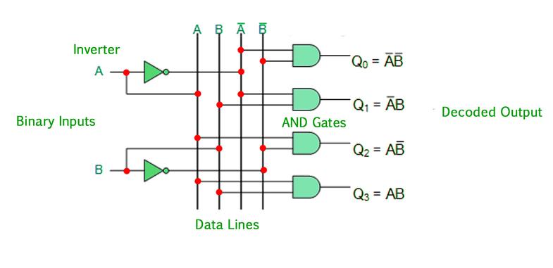
IamdiscussingthefunctionofthedecoderLet’stakealookattheinternalstructureofthedecoder.Thefigurebelowisa2-inputdecodermainlycomposedofANDgatecircuits,withatotalof22outputs(thatis,4).Fromthefigure,eachoutputcorrespondstoone.Thesmallestitem.Inthiscircuit,whenthevalueoftheinputBAis10,whichcorrespondstothedecimalnumber2,itsF2outputishigh,andtherestoftheoutputis0.
Picture2
Thepicturebelowisalsoa2-inputdecoder,butbecauseitmainlyusesaNANDgate,eachTheoutputcorrespondstothenegationofaminimumterm.Inthiscircuit,whentheinputBAis10,itsoutputF2isnolonger1,buttheoutputis0,andtheremainingoutputsare1.
Weregardthefollowingdecodercircuitastheoutputlowleveleffective(thatis,whentheinputvariablecorrespondstothedecimali,thecorrespondingi-thoutputterminalislowlevel,andtherestarehighLevel).Ofcourse,thepreviousdecoderisactiveathighlevel.
Figure3
Thetwocircuitslistedabovearethecaseof2inputs,andthesameistrueforthecaseofmorethan2inputs,thesameItcanoutputhigh-leveleffective,andoutputlow-leveleffective.

Realizelogicfunctionwithdecoder
Becauseanycombinationallogiccircuitcanbewrittenintheformofminimumtermexpression,theoutputofthedecodercircuitliststhecircuit’sAllminimumtermexpressions(ornon-expressionofminimumterms),sowemayusedecodercircuitstoimplementvariouscombinationallogiccircuits.
TheexampleusesthedecodingcircuittorealizeF(X,Y,Z)=∑(0,1,4,6,7)=∏M(2,3,5)
Wecanimplementthislogicfunctioninseveralways.Thefollowingfigurelistsfourmethods.Fromthesefourfigures,youshouldbeabletosummarizetherules.
Amongthem:
Pictureaistherealizationmethodofhigh-leveleffectiveoutputplusORgate;
Picturebisthelow-leveleffectiveoutputplusNANDgate
Figurecistheimplementationmethodofhigh-leveleffectiveoutputplusNORgate;
Figuredistheimplementationmethodoflow-leveleffectiveoutputplusNANDgate;
Figure4
EnableInputs
Enablesareoftenencounteredinmedium-scaleintegratedcircuitsTheenablepincanbeinputoroutput.Itistheinput/outputterminalusedtoexpandthefunctionofthemedium-scaleintegratedcircuit.Thefollowingfigureaisa2-inputdecoderwithaninputE,DuetotheadditionoftheinputterminalE,itsfunctionhaschanged.WhenE=0,itsoutputisall0,andthedecoderisactiveathighlevelwhentheEterminalisnotadded.Atthistime,itsoutputNoneoftheterminalsisinavalidworkingstate,wecanunderstandthatwhenE=0,thedecoderdoesnotwork;whenE=1,weseethatthedecodercanworknormally,weputthisinputterminalinEWhen=1,theenableterminalthatcanworknormallyiscalledactivehigh.Thefigurebbelowisasimplifiedlogicalsymbol.
Figure5
Thefigurebelowisanexampleofusingtheenableterminaltoconverttwo2-inputdecodersinto3-inputdecoders.Inthefigurebelow,whenI2islow,theenableterminalofthefirstdecoderishighanditworksnormally,buttheseconddecoderdoesnotworkatthistime,sotheoutputofdecoder1correspondstoInput0~3ofI3I2I1;whenI2ishigh,decoder2works,anddecoder1doesnotwork,soitsoutputcorrespondstoinput4~7ofI2I1I0,sothecircuitinthefigurebelowrealizestheuseoftheenableterminalExtenda2-inputdecodertoa3-inputdecoder.
Figure6
Standardmedium-scaledecodercircuit
Thereareseveraltypesofdecodersinmedium-scaleintegratedcircuitsThemostwidelyusedis74138,whichisa3to8decoder.Thefollowingfigureshowsitslogicsymbolsandpinarrangement.Thelogicfunctionsofthedevicearelistedinthetablebelow,whichcanbeseenfromthetable.Itsoutputislow-levelactive,enableterminalG1ishigh-levelactive,/G2,/G3islow-levelactive,whenoneofthemislow-level,theoutputterminalsareall1.
Figure7
Forexample,use74138torealizethefunctionF(X,Y,Z)=∑m(0,2,4,7)
p>
Using74138torealizethefunctionisthesameastheabove-mentioneddecodertorealizethelogicfunction,buttwopointsmustbepaidattentionto:
Theoutputof1.74138islow-leveleffective,sothelogicfunctionisrealizedWhentheoutputterminalcannotbeconnectedtoORgateandNORgate(becauseonlyoneislowleveleachtime,therestarehighlevel);
2.74138differsfromthepreviousoneinthatithasanenableterminal,Sotheenableterminalmustbeprocessed,otherwisetherequiredlogicfunctioncannotberealized.Thefollowingfigureshowsthefinalcircuit.
Figure8
Displaydecoding
Theworkingprincipleofcommonlyuseddisplaydevices
Commondigitaldisplaysindigitalsystemsusuallyinclude:light-emittingdiodenixietubes(LEDnixietubes)andliquidcrystaldisplaynixietubes(LCDnixietubes).TheLEDdigitaltubeuseslight-emittingdiodestoformstrokesfordisplayingnumberstodisplaynumbers.BecausetheLEDsemitlight,theLEDdigitaltubeissuitableforvariousoccasions.Theliquidcrystaldisplaydigitaltubeusestheliquidcrystalmaterialtoabsorblightundertheactionofalternatingvoltage,andthereisnostrokewithouttheactionofthealternatingelectricfield,soitcandisplaythenumber,butbecausetheliquidcrystalmaterialmusthavelightItcanonlybeused,soitcannotbeusedinsituationswherethereisnooutsidelight(theLCDdisplayofportablecomputerscanbeusedatnightundertheactionofbacklight),butthebiggestadvantageofLCDisthatitconsumesalotofelectricity,soitiswidelyusedinDigitaldisplayofsmalldevicessuchassmallcalculators.
ThefollowingfigureshowstheinternalstructureoftheLEDdigitaltubeandthedisplayofthenumber.ItisakindofLEDdigitaltubewithananodeconnectedinone.Weusuallycallitacommonanodedigitaltube.Sincethereisacommonanodedigitaltube,thereisacommoncathodedigitaltube.Theinternalstructureisnotdrawnhere.Pleasedrawityourself.
Figure9
LEDdecodingdrivecircuit
Light-emittingdiodesonlyneedtobeturnedon.AccordingtoWhetherthecommonpoleoftheLEDisananodeoracathodeisdividedintotwotypesofdecoders,thatis,thelow-levelvaliddecoderforthecommonanode;thehigh-leveloutputvaliddecoderforthecommoncathodeLED.
4511isaneffectivehigh-levelCMOSdisplaydecoder,itsinputis8421BCDcode,thefollowingfigureandtablerespectively4511pinarrangement,logicsymbolsandlogicfunctiontable.
Figure10
Inthefigure:
/LT:Testlamppole,low-leveleffective,whenitislow-powerNormally,allstrokesareallon.Iftheyarenoton,itmeansthatthereisaproblemwiththestroke;
/BL:Lightisoff,lowlevelisactive,whenitislowlevel,regardlessoftheinputdatastate,itsTheoutputisalllowlevel,thatis,allstrokesareextinguished;
/ST/LE:strobe/latchpole,whichisamultiplexedfunctionalterminal,whentheinputislow,itsoutputandTheinputvariableisrelated;whentheinputishigh,itsoutputisonlyrelatedtothestatebeforetheendishigh,andnomatterhowtheinputDCBAterminalchanges,itsdisplayedvalueremainsunchanged.
D,C,B,A:8421BCDcodeinput,theDbitisthemostbit;
a~g:theoutputterminalishighleveleffective,soitsoutputshouldbeCorrespondingtothedigitaltubewithitscathode.
LCDdecoderdriver
TheLCDdecoderdrivercircuitisdifferentfromtheLEDdecoderdrivercircuit.Itsoutputisnotahighleveloralowlevel,butapulsevoltage.Whenitisvalid,itsoutputisalternatingpulsevoltage,otherwiseitishighlevelorlowlevel.
